Carrier KGANP5201VSP Manuel d'instructions
Naviguer en ligne ou télécharger Manuel d'instructions pour Chauffe-eau et chaudières Carrier KGANP5201VSP. Carrier KGANP5201VSP Instruction manual Manuel d'utilisatio
- Page / 26
- Table des matières
- MARQUE LIVRES
- Installation Instructions 1
- DESCRIPTION AND USAGE 2
- /'_ I>/- ," 3
- APPLIANCE MODELS 4
- 1337932-701] 5
- Brass Street 90 " _ 6
- Connocton 8
- /_r ner Flame 9
- __ _ Burnel 9
- 337704-205 REV.B 10
- SECTION 2 11
- ......3 ,d_! 12
- ORIFICE SELECTION/DERATE 13
- CONVERSION KiT RATING PLATE 13
- - CARRIER CORPORATION 13
- [337932=701j 13
- CONVERT GAS VALVE 14
- Brass Street Tee 15
- Inlet Pressure Tap with Plug 15
- Brass Hex Nipple 15
- Connecton 16
- LABEL APPLICATION 17
- SECTION 3 18
- INSTALL ORIFICES 19
- INSTALL MIXER SCREWS 19
- ,o,o oleo[o olo lo11.oI 20
- J or G Valve 22
- Connection " P,7 ABeD 23
- SET GAS INPUT RATE 24
- (DAY-MONTH-YEAR) 25
- (JOUR-MOIS-ANNEE) 25
- Catalo_ No: AG-KGANPVSP-04 26
Résumé du contenu
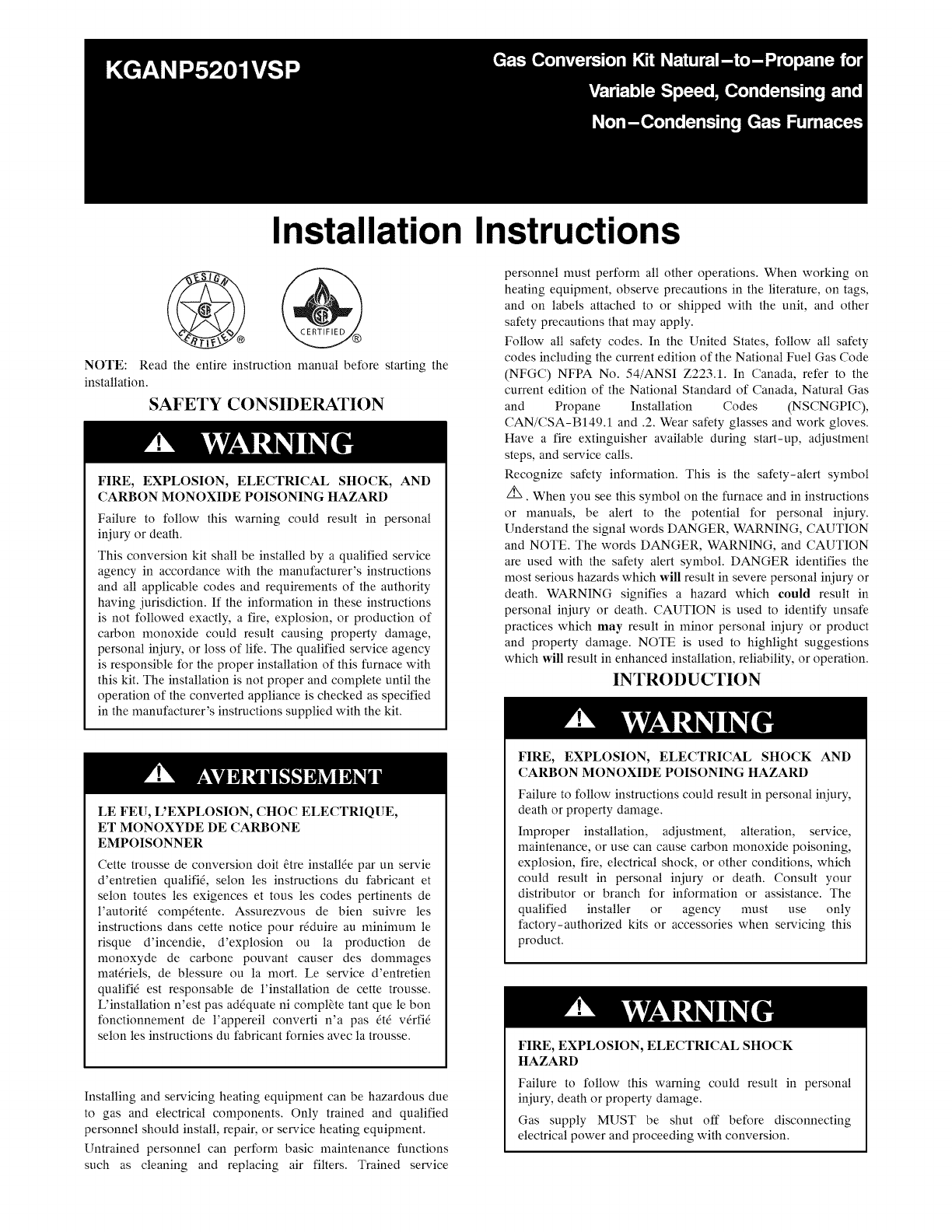
Installation InstructionsNOTE: Read the entire instruction manual before starting theinstallation.SAFETY CONSIDERATIONFIRE, EXPLOSION, ELECTRICAL SHOC
7. After burners ignite and blower starts allow the furnace torun for at least 10 minutes before checking TemperatureRise.Maximum Heat Temperature Ris
SECTION 2Table 3 - Variable Speed Condensing FurnacesMODEL NUMBERS BEGINNING WITH:59TN6 986TPG96V TINSTALLATIONFIRE, EXPLOSION, ELECTRICAL SHOCK ANDCA
FLAMESENSOR ...MANUAL RESETROL LOUT SW_TCHGAS VALVEOPERATING _NSTRUCT ONSNOT SHOWN (LOCATED ONMA_N FURNACE DOOR, SEEOPERAT NG NSTRUCTIONSINSIDE DOO
ORIFICE SELECTION/DERATE[]NIT DAMAGE HAZARDFailure to follow this caution may result in unit damage.DO NOT re-drill burner orifices. Improper drilling
REINSTALL BURNER ASSEMBLYTo reinstall burner assembly:1. Attach flame sensor to burner assembly.2. Insert one-piece burner in slot on sides of burner
(Iftheventpipepassesbetweentheinducerandburnerassembly,orthefurnaceisa143/16-in.(360ram)widecasing,installtheswitchasfollows(SeeFig29.):1.Removethel/8
D'EQUIPEMENT D'OPERATIONToute erreur de cfiblage peut _tre une source de danger et depanne.Lors des op6rations d'entretien des commande
1.Besuremaingasandelectricsuppliesto furnace are off.2. Remove l/8-in. (3 ram) pipe plug from manifold pressuretap on downstream side of gas valve.3.
SECTION 3Table 4 - Non-condensing FurnacesMODEL NUMBERS BEGINNING WITH:58CVA 315AAV58CVX 315JAVPG8MVA PG8JVAINSTALLATIONFIRE, EXPLOSION, ELECTRICAL SH
Clp, Harness//Attach G reen/Yeilowground wire hereBracket Ignito_Burner Assyumer Support AssySwitch, Temp (2)Fig. 33 - 80% BurnersGas Valve\\Al1390Man
ELECTRICALSHOCK,FIREOR EXPLOSIONHAZARDFailureto follow this warning could result in personaliniury, death or property damage.Before installing, modify
fCONVERSION KiT RATING PLATE CARRIER CORPORATIONTHiS APPLIANCE HAS BEEN CONVERTED TO USE PROPANE GAS FOR FUEL, REFER TO KiT iNSTRUCTiONS FOR CONVERSIO
f1-7/8(47.6 mm)A05026Fig. 41 - Igniter Position - Top Viewt¾2" ,,,.4 .,1_| _-'/32"SURFACEiGNITERASSEMBLY/IGNITER7/8.22.2 mm"_ BURN
ON/OFF\\\1/2"NPT IrTWO-STAGERegulator Seal CapRegulator AdjustmentRegulator Seal Capruder Cap1/8" NPT InletPressure TapOutlet1/8" NPT M
FIREANDEXPLOSIONHAZARDFailureto follow this warning could result in personal injuryand/or death.NEVER test for gas leaks with an open flame. Use acomm
back-upwrenchonteewhentighteninggasinletpipeplug.(SeeFig.46.)2" Brass Nipple/Low GasPressure SwitchFemale x Female x Male Tee1/8" NPT Pipe P
6. Adjust low-heat manifold pressure for propane gas. (SeeFig. 43.)7. Turn low-heat adjusting screw counterclockwise (out) todecrease input rate or cl
Copyright 2012 CAC / BDP • 7310 W. Morris St. • Indianapolis, IN 46231 Edition Date: 08/12Manufacturer reserves the right to change, at any time, spec
HOTSURFACEIGNITER MANUALRESETGASBURNER i ROLLOUT SWITCHi /ELECTRICALJUNCTIONBOX(REPRESENTATIVE DRAWING ONLY, SOME MODELS MAY VARY IN APPEARANCEFig. 1
BURNER SUPT ASSY IGNITERBURNER ASSY2_"'_ FLAM E SENSOR(BELOW BURNER)Fig. 3 - Burner AssemblyORIFICE SELECTION/DERATEBRACKET, IGNITER/_ FLAME
1337932-701]CONTAINS: QTYPART # DESCRIPTION328456-402 BIT, DRILL 1FAJ5812B SCREW 7REQUIRED FOR CONVERSION OFCONDENSING GAS FURNACE TOPROPANE GAS.Fig.
>A11375Fig. 11 - Installing Propane JumperNOTE: The Propane jumper for the modulating gas valve isvery small. Needle-nose pliers are required to in
For larger casing when Vent Pipe does not pass across casing. All Sizesswitch contacts must point toward the Cell Panel. Black Iron Street 90 can beus
SW4Outside Air Thermistor__/F_ Crflntin u;_2pFan_switches CF 1 throughCF 3Communication_[ SW4[]_I=_ PL9O_Connocton24 VACHUM Output(O.5 AMPiSetup Switc
SET GAS INPUT RATEUNIT DAMAGE HAZARDFailure to follow this caution may result in gas valvedamage.Do not force the rotary adjustment switch on themodul
Produits connexes et manuels pour Chauffe-eau et chaudières Carrier KGANP5201VSP
 (112 pages)


 (310 pages)
© 2020, manymanuals.fr. Tous droits réservés | 1.177 s |
 Manymanuals.com
 Manymanuals.de
 Manymanuals.fr
 Manymanuals.it
 Manymanuals.pl
 Manymanuals.cz
 Manymanuals.es
 Manymanuals-pt.com
Commentaires sur ces manuels