Carrier Infinity 24ANB6 Manuel d'instructions

Naviguer en ligne ou télécharger Manuel d'instructions pour Climatiseurs à système divisé Carrier Infinity 24ANB6. Carrier Infinity 24ANB6 Instruction manual Manuel d'utilisatio

  • Télécharger
  • Ajouter à mon manuel
  • Imprimer
  • Page
    / 14
  • Table des matières
  • DEPANNAGE
  • MARQUE LIVRES
  • Noté. / 5. Basé sur avis des utilisateurs
Vue de la page 0
24ANB6
Infinityr Air Conditioner with Puronr Refrigerant
1---1/2 to 5 Nominal Tons (Siz e 18---60)
Installation Instructions
NOTE: Read the entire instruction manual before starting the
installation.
SAFETY CONSIDERATIONS
Improper installation, adjustment, alteration, service, maintenance,
or use can cause explosion, fire, electrical shock, or other
conditions which may cause death, personal injury, or property
damage. Consult a qualified installer, service agency, or your
distributor or branch for information or assistance. The qualified
installer or agency must use factory--authorized kits or accessories
when modifying this product. Refer to the individual instructions
packaged with the kits or accessories when installing.
Follow all safety codes. Wear safety glasses, protective clothing,
and work gloves. Use quenching cloth for brazing operations.
Have fire extinguisher available. Read these instructions
thoroughly and follow all warnings or cautions included in
literature and attached to the unit. Consult local building codes and
current editions of the National Electrical Code ( NEC ) NFPA 70.
In Canada, refer to current editions of the Canadian electrical code
CSA 22.1.
Recognize safety information. This is the safety--alert symbol
!
!
When you see this symbol on the unit and in instructions or
manuals, be alert to the potential for personal injury. Understand
these signal words; DANGER, WARNING, and CAUTION. These
words are used with the safety--alert symbol. DANGER identifies
the most serious hazards which will result in severe personal injury
or death. WARNING signifies hazards which could result in
personal injury or death. CAUTION is used to identify unsafe
practices which would result in minor personal injury or product
and property damage. NOTE is used to highlight suggestions
which will result in enhanced installation, reliability, or operation.
!
WARNING
ELECTRICAL SHOCK HAZARD
Failure to follow this warning could result in personal
injury or death.
Before installing, modifying, or servicing system, main
electrical disconnect switch must be in the OFF
position. There may be more than 1 disconnect switch.
Lock out and tag switch with a suitable warning label.
CUT HAZARD
Failure to follow this caution may result in personal injury.
Sheet metal parts may have sharp edges or burrs. Use care and
wear appropriate protective clothing and gloves when
handling parts.
CAUTION
!
INSTALLATION RECOMMENDATIONS
NOTE: In some cases noise in the living area has been traced to
gas pulsations from improper installation of equipment.
1. Locate unit away from windows, patios, decks, etc. where
unit operation sound may disturb customer.
2. Ensure that vapor and liquid tube diameters are appropriate
for unit capacity.
3. Run refrigerant tubes as directly as possible by avoiding un-
necessary turns and bends.
4. Leave some slack between structure and unit to absorb vi-
bration.
5. When passing refrigerant tubes through the wall, seal open-
ing with RTV or other pliable silicon--based caulk. (See Fig.
1.)
6. Avoid direct tubing contact with water pipes, duct work,
floor joists, wall studs, floors, and walls.
7. Do not suspend refrigerant tubing from joists and studs with
a rigid wire or strap which comes in direct contact with
tubing. (See Fig. 1.)
8. Ensure that tubing insulation is pliable and completely sur-
rounds vapor tube.
9. When necessary, use hanger straps which are 1 in. (25.4
mm) wide and conform to shape of tubing insulation. (See
Fig. 1.)
10. Isolate hanger straps from insulation by using metal sleeves
bent to conform to shape of insulation.
INSULATION
VAPOR TUBE
LIQUID TUBE
OUTDOOR WALL INDOOR WALL
LIQUID TUBE
VAPOR TUBE
INSULATION
CAULK
Avoid contact between tubing and structureNOTE:
THROUGH THE WALL
HANGER STRAP
(AROUND VAPOR
TUBE ONLY)
JOIST
1 (25.4 mm)MIN.
SUSPENSION
A94028
Fig. 1 -- Connecting Tube Installation
Outdoor unit contains system refrigerant charge for operation with
AHRI rated indoor unit when connected by 15 ft. (4.57 m) of
field--supplied or factory accessory tubing. For proper unit
operation, check refrigerant charge using charging information
Vue de la page 0
1 2 3 4 5 6 ... 13 14

Résumé du contenu

Page 1 - Installation Instructions

24ANB6Infinityr Air Conditioner with Puronr Refrigerant1---1/2 to 5 Nominal Tons (Siz e 18---60)Installation InstructionsNOTE: Read the entire instruc

Page 2 - INSTALLATION

10Table 3 – Status CodesOPERATION FAUL TAMBER LEDFLASH CODEPossible Cause and ActionStandby – no callfor unit operationNone On solid, no flash Normal

Page 3

1101020304050607080900 (-17.77)20 (-6.67)40 (4.44)60 (15.56)80 (26.67)100 (37.78)120 (48.89)TEMPERATURE °F (°C)RESISTANCE (KOHMS)THERMISTOR CURVEA0805

Page 4 - Make Electrical Connections

12A10090LEGEND24--V FACTORY WIRING24--V FIELD WIRINGFIELD SPLICE CONNECTIONA97368Fig. 12 -- Non--Communicating Standard Thermostat 3--Wire 24V Circuit

Page 5 - Attachments

13FINAL CHECKSIMPORTANT: Before leaving job, be sure to do the following:1. Ensure that all wiring is routed away from tubing and sheetmetal edges to

Page 6 - Check Charge

14Copyright 2011 Carrier Corp. D 7310 W. Morris St. D Indianapolis, IN 46231 Printed in U.S.A. Edition Date: 04/11Manufacturer reserves the right to c

Page 7 - UTILITY RELAY

2located on control box cover and/or in the Check Charge section ofthis instruction.IMPORTANT: Maximum liquid--line size is 3/8--in. OD for allresiden

Page 8

3There are no buried--line applications greater than 36 in. (914.4mm).If refrigerant tubes or indoor coil are exposed to atmosphere, theymust be evacu

Page 9 - TROUBLESHOOTING

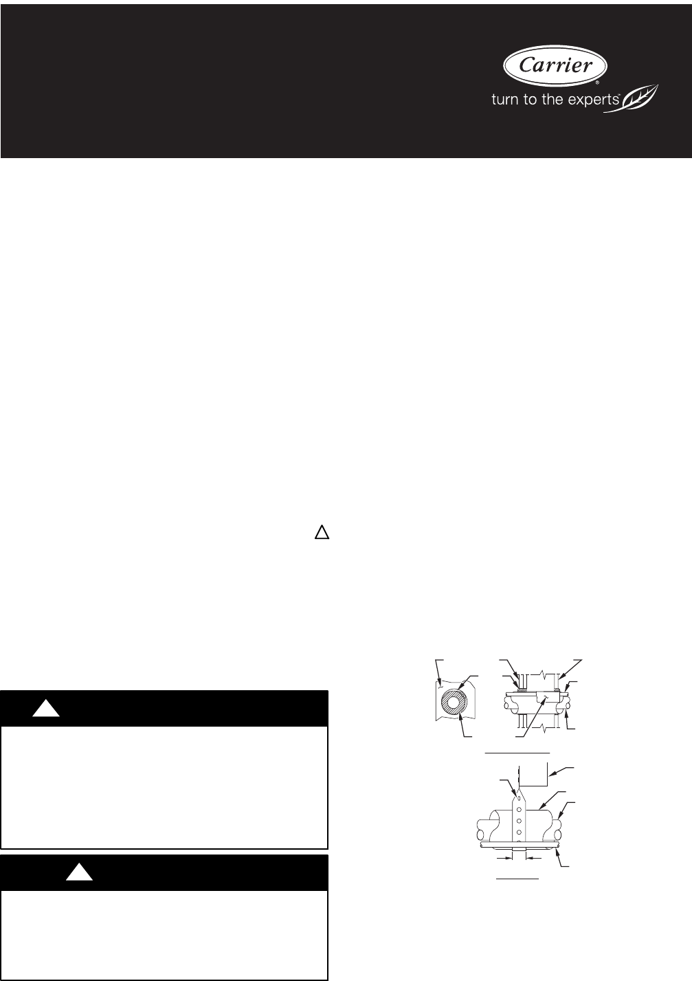
4Install Liquid Line Filter Drier IndoorCAUTION!UNIT DAMAGE HAZARDFailure to follow this caution may result in equipment damageor improper operation.I

Page 10 - Table 3 – Status Codes

5!WARNINGELECTRICAL SHOCK HAZARDFailure to follow this warning could result in personalinjury or death.The unit cabinet must have an uninterrupted or

Page 11 - THERMISTOR CURVE

6Start--UpCAUTION!UNIT OPERATION AND SAFETY HAZARDFailure to follow this caution may result in minor personalinjury, equipment damage or improper oper

Page 12 - Specific Unit combinations)

7Disconnect factory provided wires from A, B, C, and D terminals.Using factory provided wires, connect to C and Y on the controlboard for 2 wire therm

Page 13 - CARE AND MAINTENANCE

8Infinity Controlled low ambient cooling:This unit is capable of low ambient cooling without a kit ONLYwhen using a complete Infinity system. A low am

Page 14 - Catalog No: 24ANB6---1SI

9TROUBLESHOOTINGSYSTEMS COMMUNICATION FAILUREIf communication between outdoor unit, control board, and indooruser interface control has failed, the co

Commentaires sur ces manuels

Pas de commentaire